
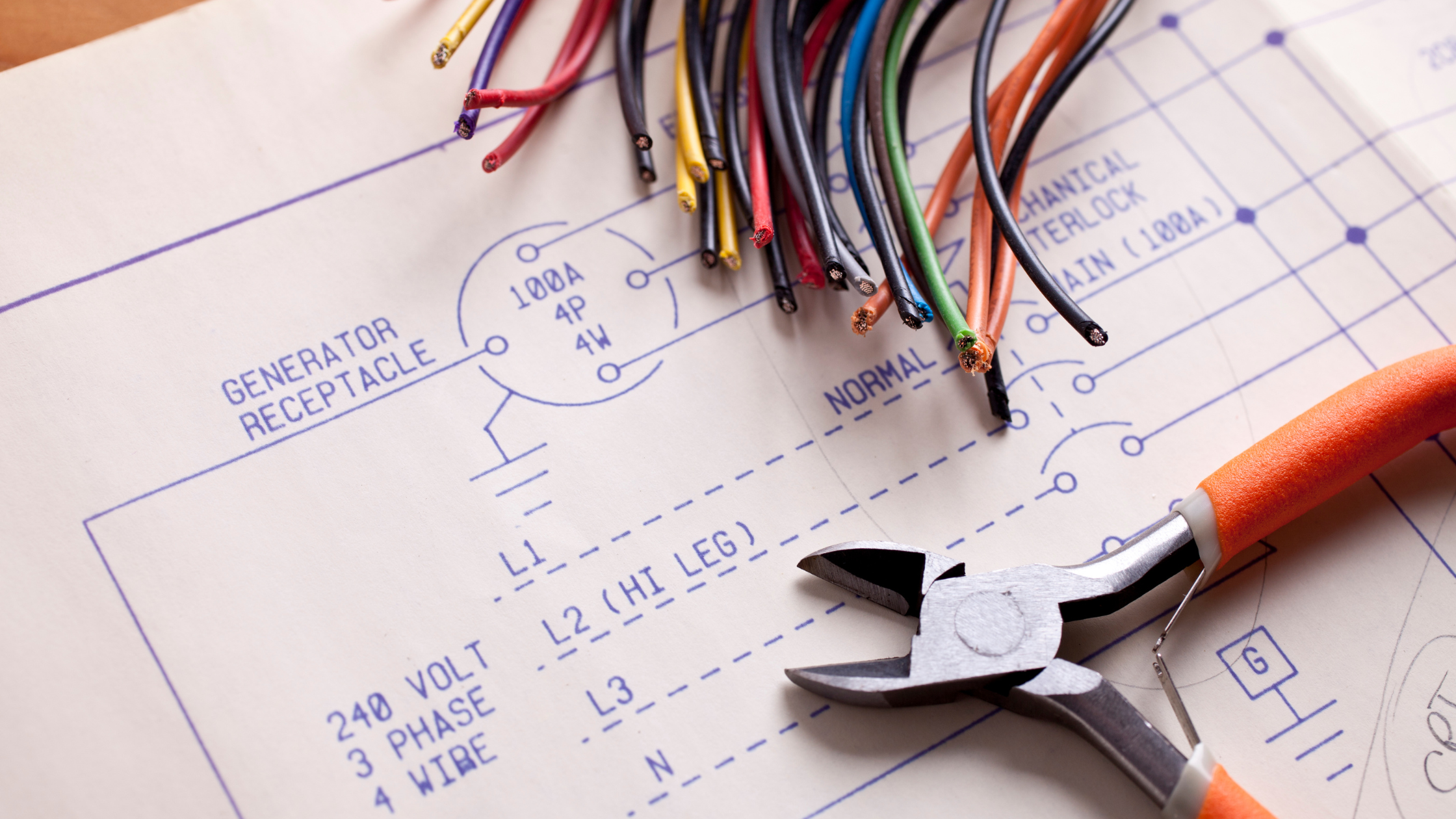
Why Industries Prefer Automation Engineers Who Understand Electrical Drawings
Imagine two automation engineers standing in front of a machine that has suddenly stopped.
The first engineer opens the PLC software immediately.
The second engineer asks for the electrical drawing.
Which engineer will find the fault faster?
In many real industrial situations, the second engineer has the advantage.
Why?
Because automation systems are not built using PLC logic alone. They are built using electrical circuits, control panels, sensors, motors, relays, contactors, VFDs, PLCs, HMIs, and communication systems.
Electrical drawings connect all these elements together.
This is why industries prefer automation engineers who can confidently read and understand electrical drawings.
What Are Electrical Drawings?
Electrical drawings are graphical representations of electrical and automation systems.
They show:
- Power flow
- Control circuits
- PLC connections
- Sensor wiring
- Motor connections
- VFD wiring
- Safety circuits
- Terminal connections
Think of electrical drawings as a roadmap of a machine.
Without a roadmap, troubleshooting becomes difficult.
Why Automation Engineers Need Electrical Drawings
Many students focus heavily on PLC programming.
That is important.
However, a PLC program only tells part of the story.
Consider a simple industrial machine.
The PLC depends on:
- Sensors
- Push buttons
- Relays
- Contactors
- Motors
- Power supplies
If any of these components fail, the machine may stop working even if the PLC program is perfect.
Electrical drawings help engineers trace these connections and identify the actual problem.
A Real Factory Example
Imagine a conveyor motor is not starting.
A beginner checks the PLC logic repeatedly.
An experienced engineer checks the electrical drawing first.
Using the drawing, they can quickly verify:
- Is power reaching the motor?
- Is the overload relay healthy?
- Is the contactor energizing?
- Is the emergency stop activated?
- Is the PLC output reaching the relay?
Instead of guessing, the engineer follows the circuit.
That is the power of electrical drawings.
The Difference Between Theory and Industry
In college, students often study:
- Electrical machines
- Circuit theory
- PLC programming
- Electronics
In industry, engineers face situations such as:
- Faulty limit switches
- Damaged cables
- Panel wiring issues
- Control circuit failures
- Emergency stop faults
These problems are usually solved by understanding electrical schematics and wiring diagrams.
This is why practical knowledge becomes valuable.
What Information Can You Find in Electrical Drawings?
A properly designed drawing can tell you almost everything about a machine.
Power Circuits
Show how electrical power reaches motors and equipment.
Control Circuits
Show how switches, sensors, relays, and PLCs interact.
PLC Wiring
Displays how input and output devices connect to the PLC.
Safety Circuits
Shows emergency stop circuits, interlocks, and safety devices.
Terminal Layout
Helps locate field wiring connections quickly.
For automation engineers, these drawings become essential troubleshooting tools.
Why Companies Value This Skill
Most factories operate continuously.
When a machine stops unexpectedly:
- Production stops.
- Downtime increases.
- Costs increase.
Companies need engineers who can solve problems quickly.
An engineer who understands electrical drawings can:
- Trace faults faster
- Reduce machine downtime
- Commission systems efficiently
- Support maintenance teams
- Improve productivity
This directly benefits the organization.
Common Mistakes Freshers Make
1. Learning Only PLC Software
Many students become comfortable with ladder logic but avoid electrical diagrams.
Both skills are equally important.
2. Ignoring Control Panel Components
Students often know PLC programming but cannot identify:
- Relays
- Contactors
- MCBs
- Power supplies
This creates a knowledge gap.
3. Not Practicing Fault Finding
Troubleshooting requires understanding both software and hardware.
Electrical drawings bridge that gap.
4. Depending on Trial and Error
Without drawings, engineers often waste time guessing.
With drawings, troubleshooting becomes systematic.
Electrical Drawings and PLC Programming Work Together
Some students think:
“I want to become a PLC programmer. Why should I learn drawings?”
Because PLC programs do not operate independently.
For example:
Sensor → Input Module → PLC Logic → Output Module → Relay → Contactor → Motor
Understanding this complete chain is impossible without understanding electrical drawings.
Great automation engineers understand both the software and the hardware.
Questions Recruiters Frequently Ask
During automation interviews, companies often ask:
- Can you read a control circuit?
- What is a relay?
- How does a contactor work?
- Can you interpret a motor starter diagram?
- Can you identify PLC input and output wiring?
- How do you troubleshoot a control panel?
Students with electrical drawing knowledge usually answer these questions more confidently.
Skills Every Automation Engineer Should Develop
If you want a successful career in Industrial Automation, focus on:
- PLC Programming
- Electrical Drawings
- Control Panel Design
- HMI Development
- SCADA Systems
- VFD Configuration
- Sensors and Actuators
- Industrial Networking
- Troubleshooting
These skills work together in real industrial environments.
Career Opportunities for Engineers with Electrical Drawing Skills
Understanding electrical schematics can help prepare for roles such as:
- Automation Engineer
- PLC Programmer
- Electrical Design Engineer
- Control Panel Design Engineer
- Commissioning Engineer
- Maintenance Engineer
- SCADA Engineer
- Service Engineer
These roles are commonly available in:
- Automotive Industries
- Manufacturing Plants
- Water Treatment Projects
- Food Processing Industries
- Pharmaceutical Companies
- Process Industries
How Students Can Start Learning Electrical Drawings
Start with basic diagrams and gradually move toward industrial panels.
Practice reading:
- Motor starter circuits
- Control circuits
- PLC wiring diagrams
- VFD connections
- Control panel layouts
Then try to understand how the drawing relates to actual hardware.
This practical approach significantly improves learning.
Ready to Become an Industry-Ready Automation Engineer?
PLC programming is an important skill.
But industries do not hire engineers to write ladder logic alone.
They hire engineers who can understand complete automation systems.
Electrical drawings help you understand how machines are connected, how faults occur, and how problems can be solved efficiently.
The next time you see an electrical schematic, don’t think of it as a complicated diagram.
Think of it as the language that every successful automation engineer must learn.
Start Your Industrial Automation Career with CADCAMGURU
At CADCAMGURU, students learn:
- PLC Programming
- Electrical Drawings
- Control Panel Design
- HMI Development
- SCADA
- VFD Programming
- Industrial Troubleshooting
- Real Automation Projects
👉 Apply for Industrial Automation Courses
You can also explore:
- How to Become an Automation Engineer
- Build Your First PLC & SCADA Project
- Industrial Automation Overview
Contact Us
📞 +91 9168603427 / +91 9168601733
📧 enquiry@cadcamguru.com
