You have a dream of becoming a design engineer.
And You are one of the thousands of engineering graduates passing out of college every year.
You might have specialized in mechanical engineering, automobile engineering, production engineering or industrial engineering.
Now, when you start seeking job in the industry, you may notice that industry works differently than what you have envisaged in your college days. Though you have first-class marks and good grades in graduation, they are not enough. There are several gaps those needs to be bridged. Those who are successful in doing it get good job and growing career.
How to identify these gaps? One easy way is to check what is generally asked in the interviews. Typically, your conceptual understanding of its application is what is focused the most. For interview, along with engineering visualization, materials there is one more crucial topic and that is Geometric Dimensioning and Tolerancing or GD&T.
If you want to know more about GD&T read our blog, Why GD&T is crucial for success of a Mechanical Engineer?
GD&T Symbols
You are aware that GD&T deals with geometric features/characteristics of a mechanical component. Let us see the symbols used in GD&T with their short explanation.
Geometric characteristics are indicated by different symbols. These symbols and their interpretation should be studied very well by a design engineer, production engineer as well as engineer doing inspection. There are 14 symbols which are grouped in various categories. We will try to explore them understand basics in this blog series.
Feature Control Frame
The GD&T specifications for any geometrical feature are mentioned on the respective component drawing with the help of a feature control frame. It consists of five chambers or boxes.

Straightness
This characteristic is important for those objects which have their length and it straightness as one of the most important parameters.
- Spindle of drilling machine
- Bed of planer machine
- Cam-shaft of a multi cylinder petrol engine
- Screw of a screw jack
Application:
A short horizontal line looking like a dash is the symbol for straightness and can be seen in the first chamber of the feature control frame.
Flatness
Flatness is a property of a plain surface with appreciable proportion at this length and width or its diameter
- Table of drilling machine
- Table of vertical boring machine
- Surfaces of angle plate
- Joining face of the cylinder head with a cylinder block
Application:
The symbol for flatness is a small parallelogram. The symbol to be put in the first chamber of the feature control frame. No datum is required to indicate the flat When an imaginary axis plan like A-A is required to be flat within some specified limits. However, this practice is not very commonness of any feature.
When an imaginary axis plan like A-A is required to be flat within some specified limits. However, this practice is not very common.
Circularity
Circular profiles correspond to some external or internal diameters that are required to be reasonably circular.
- The loss in circularity can disturb the motion of a follower when the revolving cam and reciprocating follower are at the dwelling state.
- Loss of circularity can disturb the amount of interlocking between the outer race of a ball bearing and corresponding bore of a gear box housing.
- Loss of circularity at the rolling wheels can disturb the smoothness of the straight-line motion of the carriage.
Application:
The circularity tolerance symbol is small circle drawn in the first chamber of feature control frame. The amount of permissible deviation is at the second chamber. The permissible deviation indicates that the innermost and the outermost zone of the deviated profile must be within two concentric circles with the radial difference equal to the permissible deviation.
Cylindricity
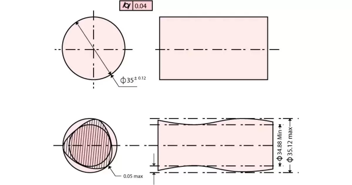
Cylindricity is a geometric feature combines the deviations at straightness and circularity at different locations for a long cylindrical component.
This is important for cylindrical components to be fitted in their inverse cylindrical profiles and assure maximum surface to surface contact over the entire contacting cylindrical surface.
- Piston cylinder assemblies at automobile engines
- Reciprocating compressors
- Reciprocating pumps
- Assembly of a cone pulley over the spindle of a lathe
Application:
 Cylindricity is a symbol consists of a circle with two 60 degree slanting tangential lines on either side of the height put in the first chamber.
The symbol shown means that the entire cylindrical surface must be contained within two theoretical cylinders having a radial difference of the amount shown as permissible deviation.
As you are aware, GD&T is one of the important aspects covered in your design engineer interview. You must know the meaning of these symbols and its interpretation. In this blog, we have covered 5 symbols which are individual features. In the next blog we will explore the next set of geometric features related to orientation and location.


